No products
Product successfully added to your shopping cart
There are 0 items in your cart. There is 1 item in your cart.
Top sellers
-

-

-
-
-
-
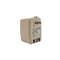
24V 40VA Transformer
$116.23 -
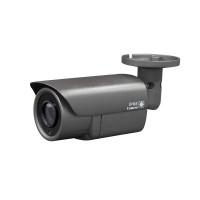
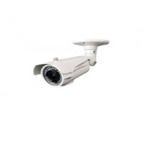
4MP CVI 4-in-1 3.6mm Bullet Camera
This is a 4MP HD over coax TVI/CVI/AHD/Analog 4-in-1 camera running on a...
$54.90 -
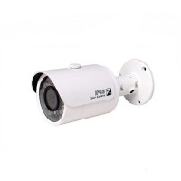
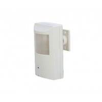
3 Megapixel Bullet IR, Outdoor
This mini bullet camera offers a 3.0 megapixel High Definition image...
$109.80 -
-

Home
- Hikvision Products
- DH OEM Series IP and CVI
- HD-CVI Products
- HD-TVI products
-
Accessories
- Video Cables and Adapters
- CCTV Tools
- Megapixel Lens / Auto iris
- Hard Drives
- LCD Monitors and Brackets
- Speakers and Amplifiers
- Power Supply Accessories
- Hikvision Mounts and Brackets
- Dahua Mounts and Brackets
- Universal Mounts and Brackets
- POE and Ethernet Accessories
- Connectors
- Network Cables
- RG59 Siamese Cables and BNC cables
- Video Intercom Access Control
- Alarm System Products
- Point of Sale Systems
- Uniview Security Products
Information
Manufacturers
No manufacturer
Suppliers
No supplier
Viewed products


More info
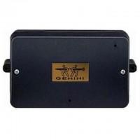
Napco Gemini Advanced Performance RF Receiver, 32 Points
DESCRIPTION
GEM-RECV Series receivers are the hardwired interface to
Napco's Wireless-Ready
TM Control Panels. The wireless system comprises a compatible GEM-Series control panel, at least
one GEM-RECV receiver and one or more companion GEMSeries transmitters. The transmitters may be wireless smoke
detectors, space-protection devices, window/door sensors, or
other devices that report zone status and supervision information to the receiver without the use of wires.
THE GEM-RECV RECEIVER
Five receivers are available: GEM-RECV8, GEM-RECV16,
GEM-RECV32, GEM-RECV96, GEM-RECV255 will accommodate up to 8, 16, 32, 96 and 255 wireless zones, respectively.
The receiver is connected to the control panel's 4-wire bus. The
receiver monitors each transmitter, updating transmitter status
as reports are received, and conveys this information to the
control panel. Also monitored is the elapsed time since the last
report from each transmitter. If no report is received within a
programmed time, a Supervisory Failure will result.
COMPATIBLE CONTROL PANELS
The GEM-receivers listed above are compatible with the following control panels:
COMPATIBLE TRANSMITTERS
Any of the following Napco wireless transmitters may be used
with the GEM-RECV Series Receivers.
GEM-TRANS2 Window/Door Sensor - This supervised, twopoint transmitter provides an internal magnetic reed switch
and/or terminals for two external normally-closed devices,
or one external normally-open device.
GEM-PIR - Wireless PIR Motion Sensor.
GEM-PIRPET - Wireless 30lb. Pet Immune PIR Motion Sensor.
GEM-DT - Dual-Technology PIR / Microwave Sensor.
GEM-SMK - Wireless Photoelectric Supervised Smoke Detector.
GEM-HEAT - Wireless Heat Detector 135°F / Rate of Rise.
GEM-KEYF - Mini Keyfob/KeyChain Remote Arming or Emergency Transmitter.
GEM-WP - Wireless Waterproof Panic Button.
GEM-GB - Glass-Break Sensor.
GEM-RTRANS - Recessed Window/Door Transmitter
GEM-KEYFLR - Full-size, Long-Range Key Chain/Pendant
Remote Arming/Emergency Transmitter
SPECIFICATIONS, GEM-RECV Receiver:
Operating Temperature: ......................................0°C to 49°C
Storage Temperature: .....................................20°C to + 85°C
Power Requirements: ......12VDC, 70mA (supplied by panel)
Antenna: .............................................................. ¼ - wave (2)
Dimensions: ..............................6¾" x 35
/8" x 1½" (W x H x D)
NOTE: For UL Residential Installations, a maximum of 200
supervisory reporting transmitters may be installed. This
does not include GEM-KEYF or GEM-WP remotes.
ORDERING INFORMATION
Note: Batteries are included with all transmitters.
GEM-RECV8 8 - Point Receiver/Interface
GEM-RECV16 16 - Point Receiver/Interface
GEM-RECV32 32 - Point Receiver/Interface
GEM-RECV96 96 - Point Receiver/Interface
GEM-RECV255 255 - Point Receiver/Interface
GEM-DT Dual-Technology PIR/Microwave sensor
GEM-GB Glass-Break Detector
GEM-KEYF Hand-Held Key Fob Pendant/Key chain
Panic Button
GEM-PIR Wireless PIR Motion Sensor
GEM-PIRPET Wireless 30lb. pet immune PIR Motion Sensor
GEM-SMK Supervised Smoke Detector
GEM-HEAT Wireless 135°F Heat Detector / Rate of
Rise
GEM-TRANS2 2-Point Window/Door Transmitter
GEM-WP Wireless Waterproof Panic Button
DL123A Replacement Lithium Battery for GEMTRANS2, GEM-RTRANS, GEM-PIR (2),
GEM-PIRPET (2) and GEM-GB (2) (bulk
packed)
INSTALLATION
Designing the System
In planning the layout of the system, give careful consideration
to the location of the receiver. Regardless of where the control
panel is mounted, the receiver should be centrally located
within the premises, that is, equally distant from all transmitters.
Choose a location as high above ground level as practical (attic
installations are not recommended), keeping in mind that metal
objects may adversely affect reception. Draw a layout of the
system, identifying all proposed transmitter locations and anticipated receiver location. Also include notations indicating construction materials in use. Although wood and wallboard construction will have little effect upon signal strength at the receiver, concrete or brick can reduce signal strength by up to
35%, while steel-reinforced concrete or metal lath and plaster
can reduce transmitter strength as much as 90%.
INSTALLATION INSTRUCTIONS
R
333 Bayview Avenue
Amityville, New York 11701
For Sales and Repairs, (800) 645-9445
For Technical Service, (800) 645-9440
Publicly traded on NASDAQ Symbol: NSSC
© NAPCO 2006
• GEM-P816 • GEM-P1632 • GEM-P1664
• GEM-P3200 • GEM-P9600 • GEM-X255
2
Note: In difficult installations wherein distant transmitters pose
reception problems, the use of multiple receivers throughout
the premises is recommended. (The GEM-P816, P1632,
P1664 and P3200 control panels will accommodate two receivers; the GEM-P9600 and GEM-X255, up to four). Receivers are connected to the panel's 4-wire bus. They should be
uniquely addressed (see ADDRESSING MULTIPLE RECEIVERS) and all be of the same type, that is, all GEM-RECV8, all
GEM-RECV16, etc.
Note: If receivers are intermixed, the panel will only recognize
the capacity of the lowest one.
Mounting and Wiring the Receiver
After its location has been determined, remove the front cover
and orient the receiver so that the antennas are at the top.
Allowing at least 12 inches clearance for the antenna, mount
the receiver using two screws suitable to the mounting surface
through the two mounting holes in the rear cover (see Wiring
Diagram). Using 4-conductor cable, wire the receiver to the
control panel in accordance with the following table:
GETTING UP AND RUNNING
(Also see Quick Method, which follows).
For each transmitter, enter:
• the zone number to which the transmitter will be mapped;
• the 6-digit ID Code: 1-digit checksum number printed on
the transmitter and box;
• the wireless point number.
Note: When programming the ID Code at the keypad,
press G0 for "A"
press G1 for "B"
press G2 for "C"
press G3 for "D"
press G4 for "E"
press G5 for "F"
Press D to save and NEXT (E) to continue.
Key Fob Transmitters. Referring to the programming instructions for the control panel, enter the following:
• an assigned Key Fob Transmitter number (1—16);
• the Area number(s) to which the Key Fob Transmitter is
designated;
• the 6-digit hexadecimal identification code with 1-digit
checksum number printed on the transmitter (enter all
numbers and/or letters, including leading zeros, if any);
• Aux. 1 options (see programming worksheets);
• Aux. 2 options (see programming worksheets).
Quick Method
If a receiver is already installed in the panel, Napco Transmitter wireless points can be programmed automatically
("enrolled"). Note: (1) The transmitter point will be enrolled
only if the signal strength is 3 or greater. (2) Enroll a singlepoint device by merely powering it up. (3) Quick Method is
not applicable to Keyfob Transmitters.
Enter the Program Mode. Scroll to the RF Transmitter Points
entry screen and proceed as follows.
1. Enter the zone number to which the transmitter point will
be mapped.
2. Press Bto enter the Enroll Mode. The red and green
LEDs on the keypad will flash and will display as shown
below (GEM-RP1CAe2).
3. Open the loop of the point that is to be programmed.
4. Install the transmitter battery. The keypad will indicate
that the point has been successfully enrolled.
Multi-Point Transmitters can be mapped to successive
zones simultaneously (Example 1) or to selected point by
point. (Example 2).
Example 1: A 2 point transmitter has the ID Code number 410078.
Map the two points to Zones 11 and 12 respectively.
1. Enter the Enroll mode as described in step 2 above.
2. Enter Zone "11".
3. Open the loops of points 1 and 2.
4. Install the transmitter battery. The keypad will beep twice
to indicate that two points have been
Transmitter 410078, point 1 will be mapped to Zone 11
Transmitter 410078, point 2 will be mapped to Zone 12
The keypad will now display Zone 12, the last zone enrolled.
Example 2. A 2-point transmitter has the 1D Code number 287613.
Map point 1 to Zone 6 and point 2 to Zone 9.
1. Enter the Enroll mode as described above.
2. Enter Zone 06.
3. Open point-1 loop.
4. Install the battery. The keypad will beep once to indicate
that one point has been programmed. (Transmitter point
1 will be mapped to Zone 6).
5. Enter Zone "09".
6. Open point-2 loop.
7. Remove the transmitter battery, then re-install it. The
keypad will beep once to indicate that one point has been
programmed. (Transmitter 287613, point 2 is Zone 9.)
CHECKING TRANSMITTERS
The status of each transmitter may be checked at the keypad.
Referring to the control panel installation instructions and the
user's guide for the keypad in use, display transmitter status to
show (a) the zone to which transmitter point is mapped; (b) the
transmitter's 6-digit RF ID number (c) the point number; (d)
transmitter status (normal, open, low battery, etc.); and (e) the
signal strength of its last transmission.
Signal Strength
Relative signal strength is displayed on a scale of 1-10, with 10
being the strongest. A reading of "No Data S —" denotes that
a report from that not yet been received. Readings less than
"3" indicate reception is poor and may be unreliable. In this
case, the use of a second receiver located closer to the is adGEM-RECV GEM-Control Panel
1 (+) 9 Remote Power (+)
2 (–) 10 Remote Power (–)
3 (RX) 11 (GREEN)
4 (TX) 12 (YELLOW)
Z N # X M I T # + C S P
Z N 0 1 - E N R O L L : A - -
3
visable. For installations that include several transmitters,
multiple receivers may be connected to the panel. (Only the
highest signal strength will be displayed).
Note: When using the Fault-Find Mode on wireless zones,
the keypad will beep when the zone is opened or closed only
if the signal strength of the transmitter is 3 or greater.
ADDRESSING MULTIPLE RECEIVERS
If more than one receiver is being utilized, each must be individually addressed so that it can be identified by control
panel. This is accomplished by the placement of jumpers on
JP1 and JP2 at the tower-left corner of the board. Refer to
the Wiring Diagram for jumper configuration. Note: Each
receiver leaves the factory internally configured as #1.
Therefore, if only one receiver is being used, address assignment is not required.
WIRELESS SYSTEM TROUBLES
The following system-trouble codes displayed at the keypad
(s) are related to wireless operation.
Transmitter Troubles
Note: Also displayed with the transmitter trouble code are
the zone number ("NN") to which Point 1 is mapped and the
transmitter's identification number.
WI LOBATT - E05-NN. Transmitter low battery. Note: If all
transmitters were installed at the same time, it is recommended to replace all transmitter batteries to avoid service callbacks.
LOBATT KEYFOB - E18-NN. Key Fob transmitter low battery.
WL TRBL - E04-NN. Supervisory failure. indicates that a
transmitter has not "checked in" within the programmed
timeout. Check the transmitter for a dead battery (see
note above). Also, check for an object in the path of the
transmitter blocking reception.
WL TAMPER - E15-NN. Tamper condition Indicates that a
transmitter case is open . Re-install cover.
Receiver Troubles
Note: Also displayed with the receiver trouble code is the
receiver number ("NN").
RF REC JAMMED - E16-NN. Transmitter interference
from nearby radio-frequency source.
RF REC RES TRBL - E06-NN. Receiver response trouble
(data failure between receiver and control panel). Check
the wiring between the receiver and the panel.
RF REC TAMPER - El 7-NN. Receiver open. Install cover.
LED INDICATIONS
Red LED (DS1)
Green LED (DS2)
The green LED will flash while receiving a transmission having a signal strength of 4 or greater, indicating a signal of sufficient strength. Caution: A green LED display with no
transmitter in operation in operation is a sign of high ambient
RF interference. If the green LED remains lit continuously,
relocate the receiver.
RED LED Receiver Condition
OFF No Power
ON Powered, but not communicating with panel
FLASHING Powered, properly communicating with panel
4
NAPCO SECURITY SYSTEMS, INC. (NAPCO)
warrants its products to be free from manufacturing
defects in materials and workmanship for thirty-six
months following the date of manufacture. NAPCO will,
within said period, at its option, repair or replace any
product failing to operate correctly without charge to the
original purchaser or user.
This warranty shall not apply to any equipment, or any
part thereof, which has been repaired by others,
improperly installed, improperly used, abused, altered,
damaged, subjected to acts of God, or on which any
serial numbers have been altered, defaced or removed.
Seller will not be responsible for any dismantling or
reinstallation charges.
THERE ARE NO WARRANTIES, EXPRESS OR
IMPLIED, WHICH EXTEND BEYOND THE
DESCRIPTION ON THE FACE HEREOF. THERE IS
NO EXPRESS OR IMPLIED WARRANTY OF
MERCHANTABILITY OR A WARRANTY OF FITNESS
FOR A PARTICULAR PURPOSE. ADDITIONALLY,
THIS WARRANTY IS IN LIEU OF ALL OTHER
OBLIGATIONS OR LIABILITIES ON THE PART OF
NAPCO.
Any action for breach of warranty, including but not
limited to any implied warranty of merchantability, must
be brought within the six months following the end of
the warranty period. IN NO CASE SHALL NAPCO BE
LIABLE TO ANYONE FOR ANY CONSEQUENTIAL
OR INCIDENTAL DAMAGES FOR BREACH OF THIS
OR ANY OTHER WARRANTY, EXPRESS OR
IMPLIED, EVEN IF THE LOSS OR DAMAGE IS
CAUSED BY THE SELLER'S OWN NEGLIGENCE OR
FAULT.
In case of defect, contact the security professional who
installed and maintains your security system. In order to
exercise the warranty, the product must be returned by
the security professional, shipping costs prepaid and
insured to NAPCO. After repair or replacement, NAPCO
assumes the cost of returning products under warranty.
NAPCO shall have no obligation under this warranty, or
otherwise, if the product has been repaired by others,
improperly installed, improperly used, abused, altered,
damaged, subjected to accident, nuisance, flood, fire or
acts of God, or on which any serial numbers have been
altered, defaced or removed. NAPCO will not be
responsible for any dismantling, reassembly or
reinstallation charges.
This warranty contains the entire warranty. It is the sole
warranty and any prior agreements or representations,
whether oral or written, are either merged herein or are
expressly cancelled. NAPCO neither assumes, nor
authorizes any other person purporting to act on its
behalf to modify, to change, or to assume for it, any
other warranty or liability concerning its products.
In no event shall NAPCO be liable for an amount